Huikai Video to Fiber Systems
|
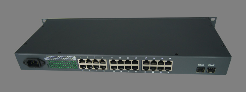
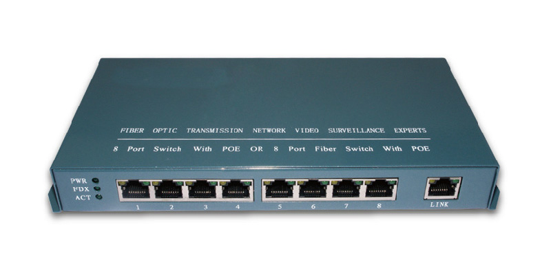
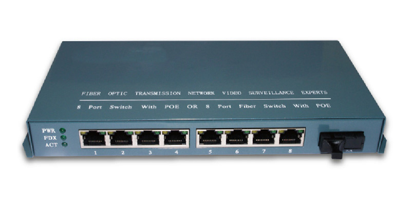
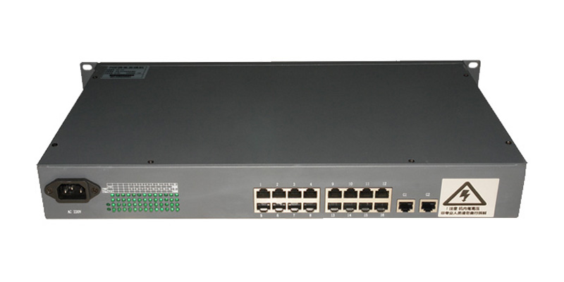
4-8-16-24 Port POE Power Switch / 4-8-16-24 Port POE Power Fiber Switch
Product Description:
4-24 Port POE Power Switch / 4-24 Port POE Power Fiber Switch, Using chip: IC + Switch chip and Maxim POE module network switching device, Provided intelligent power supply system, Over load protection, Breaking the traditional Powerline layout constraints, 5-25 piece Hundreds of megabytes electrical ports, Support 5-25 port powered, Simple and reliable design.
Features:
1) Supported by Category 5 Ethernet cable to access the wireless access point (AP with POE function)
2) 5-25 Ports support standard IEEE802.3af powered
3) 5-25 Ports 10/100 Mbps auto-negotiation RJ45 ports
4) Compliance with IEEE802.3 10Base-T and IEEE 802.3u 100Base-TX standards
5) Support Auto MDI/MDIX
6) Support uplink port lightning protection (Port reached two levels lightning protection require ments)
7) The max. Power of each port is 15.4W
8) Using the store and Foward switching mechanism
9) All ports support wire-speed switching, frame size within the range of 64 to 1536 can achieve wire-speed
10) No fan, natural heat dissipation
11) Small, compact, quiet design suitable for placement on a desktop or wall
12) Supported Network surveillance cameras (with POE feature powered)
Application Environment:
1) Million high-definition monitor transmission and powered
2) Wireless AP distribution transmission and powered
3) VoIP transmission, intelligent home systems
4) Urban Intelligent Traffic Monitoring System (ITS), safe city, wireless city
5) Highway monitoring system, electronic road monitoring, capture system
6) Large factories and mines enterprise security monitoring system, network multifunction system
7) Remote multimedia teaching / Campus monitoring, video conferencing systems
8) Building intercom, wireless communication, video surveillance
Ordering Information:
| SN | Product | Details | Transmission distance | Packing |
| 1 | 4 Port POE Switch | 4 POE Powered Ethernet port, without module |
<100M over CAT5 | 1 PCS/Carton |
| 2 | 4 Port POE Single Fiber Switch | 4 POE-Powered Ethernet port, 1 SC module |
0-20km over Fiber | 1 PCS/Carton |
| 3 | 8 Port POE Switch | 8 POE Powered Ethernet port, without module |
<100M over CAT5 | 1 PCS/Carton |
| 4 | 8 Port POE Single Fiber Switch | 8 POE-Powered Ethernet port, 1 SC module |
0-20km over Fiber | 1 PCS/Carton |
| 5 | 16 Port POE Switch | 16 POE Powered Ethernet port, without module |
<100M over CAT5 | 1 PCS/Carton |
| 6 | 16 Port POE Single Fiber Switch | 16 POE-Powered Ethernet port, 1 SC module |
0-20km over Fiber | 1 PCS/Carton |
| 7 | 24 Port POE Switch | 24 POE Powered Ethernet port, without module |
<100M over CAT5 | 1 PCS/Carton |
| 8 | 24 Port POE Single Fiber Switch | 24 POE-Powered Ethernet port, 1 SC module |
0-20km over Fiber | 1 PCS/Carton |
| LED Indicator: PWR= POWER, FDX= FIBER, ACT= Ethernet Port LED, LINK= Ethernet Port, |
|||
| Status | Connected Power Supply | Connected the Link Network Port | Connected the 1-24 Network Port |
| Ethernet Switch | PWR: Always light | FDX: Always light ACT: Weak blinking LINK: Yellow Light Always light Green Light Weak blinking |
ACT: Strengthen blinking 1-24 Port Yellow Light Always light Green Light Weak blinking LINK: Green Light Strengthen blinking |
| Fiber Switch | PWR: Always light | FDX: Always light ACT: Weak blinking |
ACT: Strengthen blinking 1-24 Port Yellow Light Always light Green Light Weak blinking |
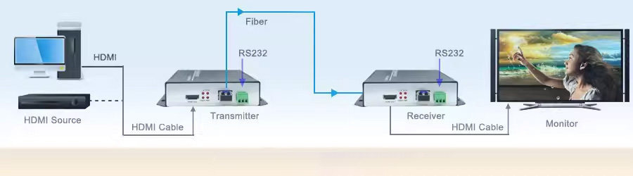
Application solution one:
Typical applications one: IP terminal supports POE Power supply,
Just connected the IP terminals to a PoE Switch, mean while the network cable to transfer data and provide DC power supply from the PoE Switch.
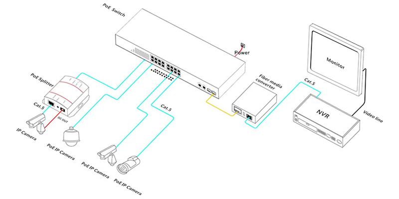
Application solution two:
Typical applications two: IP terminal does not supports POE Power supply,
Need to add PoE splitter next to the IP terminals,
Diagram: |
|
 |
|
More photos: |
|
 |
|
 |
|
 |
|
 |
Tags: Fiber Media Converter
Related Products
-

10/100M Industrial grade optical fiber transceiver Simplex Fiber 1×9 Fast Media Converter Series
No. -

10/100/1000M Gigabit Sinplex Fiber SFP Port Fast Media Converter
No. -

10/100/1000M Gigabit Single Fiber Fast Media Converter 16 Ports
No. -

10/100/1000M Gigabit Single Fiber Fast Media Converter 8 Ports
No. -

10/100/1000M Gigabit Single Fiber Fast Media Converter 4 Ports
No. -

10/100/1000M Gigabit Single Fiber Fast Media Converter 1 Port
No. -

10/100M Single Mode Single Fiber 4 Ethernet to Fiber Converter HK-0110-4V
No. -

10/100M Single Fiber Media Converter HK-0110-1V
No.

|